
Key Features
- Frequency Range0.2 - 26 GHz
- Gain14 dB
- P1dB+25.5 dBm
- IP3+35 dBm
- Single Supply +5V to +12V
- VD= +10V @ 190mA
Applications
- Wideband Receivers, SDRs
- Microwave Radio
- Test and Measurement
- EW / ECM / C-UAS
- Military and Commercial Radar
Architecture
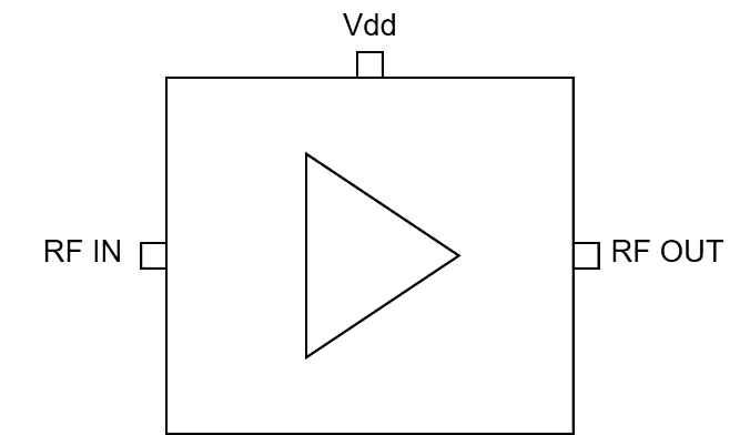
ATEK569 Block Diagram
The ATEK569 is a GaAs PHEMT wideband distributed amplifier operating from 0.2 to 26GHzThe ATEK569 amplifier provides a flat gain of 14dB with an OIP3 of +35dBm and a +25dBm P1dB while operating from a single supply voltage of +10V drawing 190mA of current. The DC power bias of +5V to +12V can be supplied to the RF output port using an external bias-T.The amplifier achieves a low noise figure of 3dB typical over the 6 to 18GHz band with +35dBm OIP3 enabling a high dynamic range driver amplifier.The ATEK569 is supplied as a bare MMIC die and has outstanding drive/linearity for a wide range of radar, SATCOM, SDR, test instrument, & EW/ECM transceiver applications. MMICs are available from stock.
Technical Specifications
| Parameter | Condition | Min | Typical | Max | Unit |
|---|---|---|---|---|---|
| Frequency Range | 0.2 | 26 | GHz | ||
| Gain | 0.25 GHz | 13.6 | dB | ||
| 2 GHz | 13.8 | dB | |||
| 8 GHz | 13.9 | dB | |||
| 12 GHz | 13.8 | dB | |||
| 18 GHz | 13.8 | dB | |||
| 26 GHz | 12.7 | dB | |||
| Isolation | 0.25 GHz | 64 | dB | ||
| 2 GHz | 60 | dB | |||
| 8 GHz | 45 | dB | |||
| 12 GHz | 40 | dB | |||
| 18 GHz | 33 | dB | |||
| 26 GHz | 28 | dB | |||
| Input Return Loss | -14 | dB | |||
| Output Return Loss | -13 | dB | |||
| Noise Figure (5V) | 3 | dB | |||
| Output IP3 | 35 | dBm | |||
| Output P1dB | 25.5 | dBm | |||
| Psat | 27.5 | dBm | |||
| DC Supply Voltage (Vdd) | 10 | 12.5 | V | ||
| DC Supply Current (Idd) | 190 | mA | |||
| Operating Temperature | -40 | 85 | °C |
Available Resources
Ready to Integrate ATEK569?
Contact our engineering team for technical support, samples, or volume pricing.