
Key Features
- 256 Filter States18 to 26 GHz
- High Rejection-40 dBc
- Fast Tuning Speed<200 nS
- P1dB+28 dBm
- Single +5V @ 9mA Supply
- compact size4x4 mm
Applications
- Wideband Receivers & SDRs
- EW / ECM / C-UAS
- Telecom & SatCom
- Test & Measurement
- Ideal for Low SWaP
Architecture
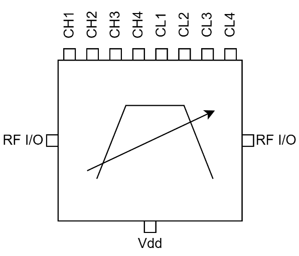
ATEK897N4 Block Diagram
ATEK897N4 is a GaAs MMIC digitally tunable band pass filter offering low 8dB in-band loss and excellent rejection of -40 to -30 dBc from 18 to 26 GHz.The RF input and outputs are bidirectional and internally matched to 50 ohms for low SWaP transmit and receive applications.The MMIC filter bank is powered by a single +5V supply drawing 9 mA with an 8-bit GPIO control interface selecting 256 filter states.Housed in 4x4 mm QFN surface mount package, the monolithic filter bank IC inherently minimizes phase noise degradation caused by mechanical vibration (microphonics).MMICs and Evaluation Boards are available from stock. Custom package configurations, MMIC die, and module options are available upon request.
Technical Specifications
| Parameter | Condition | Min | Typical | Max | Unit |
|---|---|---|---|---|---|
| Frequency Range | 17 | 18 - 26 | 29 | GHz | |
| Insertion Loss | 8 | dB | |||
| Input Return Loss | -7 | dB | |||
| Output Return Loss | -10 | dB | |||
| Input IP3 | 45 | dBm | |||
| Input P1dB | 28 | dBm | |||
| Switching Speed (50% Vctrl to 90% of RF Output) | On | <200 | nS | ||
| Off | <200 | nS | |||
| Settling Time @ <0.1dB | TBD | nS | |||
| DC Supply Voltage (Vdd) | 5 | V | |||
| DC Supply Current (Idd) | 9 | mA | |||
| Control Voltage (CTRL) | Low | -0.1 | 0.5 | V | |
| High | 2.5 | 5.5 | V | ||
| Control Current (Ictrl) | 5.5 | mA | |||
| Operating Temperature | -40 | 85 | °C |
Available Resources
Ready to Integrate ATEK897N4?
Contact our engineering team for technical support, samples, or volume pricing.